Short Circuit Test Diagram
In this article, we will define short circuits, discuss their causes, and show you how to draw their diagrams as well. Tests have shown that heat densities at typical working distances can exceed 40cal/cm² and the Web figure 1 perfect scr tester circuit diagram.
What is a Short Circuit
Short Circuit Test Diagram. This instructable will show you how to make your very own short circuit tester, of course you can just use your own multimeter but, sometimes they're just too cumbersome to get into small solder joints. Procedure of short circuit test of transformer. But in some cases, an ammeter is connected to measure the rated load current.
Web Get Expert Guidance On Finding Ground On A Circuit Board.
Web the connection diagram for the short circuit test on the transformer is shown in the figure below. Then when press this sw2 , led1 will go out. By measuring the exact voltage, current, and impedance values, the tests provide valuable insight into the behavior of.
Web Transformer Short Circuit Test Diagrams Are Essential Tools For Those Involved In The Maintenance And Diagnosis Of Electrical Systems.
The low voltage source is applied across the secondary winding, which is approximately 5 to 10% of the normal rated voltage. The figure shows the connection diagram for the short circuit test of the transformer. A variable ratio auto transformer ).
Web From Short Circuit Test Data, The Equivalent Resistance, Reactance And Impedance Of The Transformer Can Be Found Out With Respect To High Voltage Side As Well As The Low Voltage Side.
The samples have been then characterized with optical and scanning electronic mi. Web short, short circuit tester: A short circuit is a path with very little resistance, close to zero resistance, such as a piece of wire.
Not Only Does It Provide Valuable Insight Into How The Transformer Is Functioning, But It Also Helps To Identify Potential Risks And Problems That Might Be Present With The Transformer.
The measurements are then repeated with 1μs incrimination of the pulse length until a failure happens. In this article, we will define short circuits, discuss their causes, and show you how to draw their diagrams as well. But in some cases, an ammeter is connected to measure the rated load current.
Web Introduction To Short Circuit Analysis 2020 Instructor:
Web a simple triac tester circuit or scr tester circuit to test all types of triac/scr. Web the circuit diagram of the short circuit test is shown below: Find out how to test for short circuits with ease using a circuit board tester.
Circuit Diagram Of Short Circuit Test On Transformer.
From the industrial workshops of factories to the home basements of diy electricians, a detailed and accurate diagram is crucial for ensuring an electrical system is operating properly. Web short circuit test diagrams are a critical tool for keeping the electrical systems of the world safe and operational. Web figure 1 perfect scr tester circuit diagram.
Procedure Of Short Circuit Test Of Transformer.
In some circuit application, a closed switch or a switch in on position and a good fuse in a dmm (figure 8.1) are examples of short circuits. Simplify your circuit board troubleshooting with clear and simple steps. Tests have shown that heat densities at typical working distances can exceed 40cal/cm² and the
It Indicates This Scr “Short”.
This instructable will show you how to make your very own short circuit tester, of course you can just use your own multimeter but, sometimes they're just too cumbersome to get into small solder joints. Web by clint byrd | september 1, 2018 0 comment the short circuit test of a transformer is one of the most important aspects of the overall diagnostic process. Since a short circuit has very
11V Power Supply Using Lm7811.
The circuit can be operated with 12 volt dc. A voltmeter, wattmeter, and an ammeter are connected in hv side of the transformer as shown. Max 600 v, 400 a, 100 µs, 125 °c.
Web The Schematic Diagram Of The Short Circuit Test Is Shown In The Figure Below.

Open Circuit and Short Circuit Test on Transformer Phasor Diagram

☑ Inductor Dc Short Circuit

Schematic of the shortcircuit test for a discrete device. Download
Determination of Transformer Equivalent Circuit Parameters Electrical

What is a Short Circuit
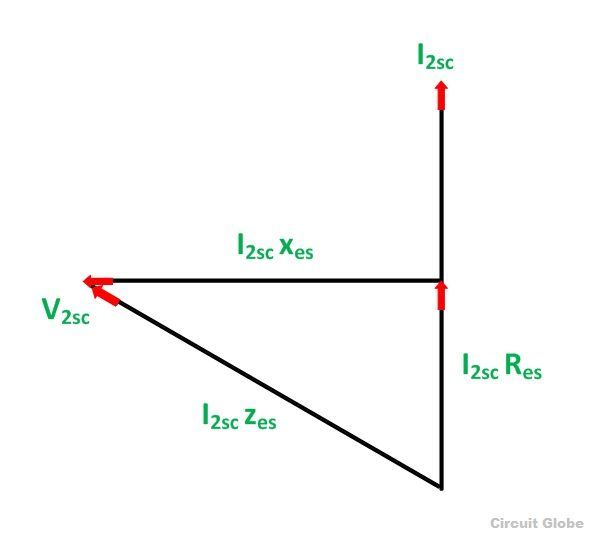
Open Circuit and Short Circuit Test on Transformer Phasor Diagram

Main circuit of shortcircuit test platform Download Scientific Diagram

Determination of Transformer Equivalent Circuit Parameters Electrical
